

How To Fix A Broken Analog Stick
Introduction
Here is a DualShock 4 controller that had a drift to both analog joysticks. Fairly straight forward replacement of the joysticks resolved the issue.
-
-
Using the Phillips #00 Screwdriver, remove the four 6.0 mm screws securing the rear cover to the controller.
-
Do not forcefully loosen the screws, as it will amount to permanent damage of the threads, making removal impossible.
-
-
-
Beginning with the left handle:
-
Pinch the left handle of the controller to introduce an opening.
-
Wedge a plastic opening tool into the opening and slide it up towards the joystick.
-
Pull down on the plier to crack open the casing.
-
Repeat these steps for the right handle.
-
-
-
Wedge a plastic opening tool into the case-splittings and pull down to crack open the casing near the following buttons:
-
Share button
-
Options button
-
Split the plastic covers of the controller apart, taking note that they will still be attached by circuit board ribbons.
-
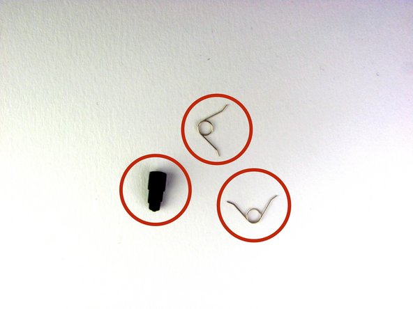
Three small pieces are often released from the framework. To prevent loss, maintain a controlled work field.
-
2 Trigger Springs
-
1 Grey Reset Button Extension
-
-
-
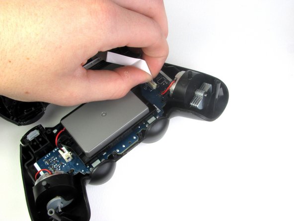
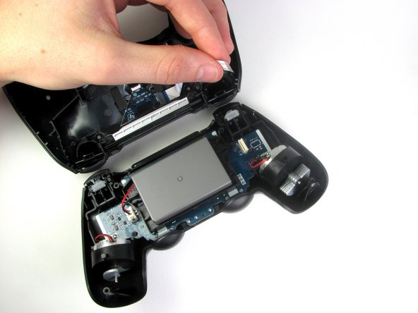
Detach the motherboard ribbon connecting the two sides of the controller by pulling it straight out with your fingers.
-
Note the orientation of the cable and make sure it faces the right way when you reconnect it.
-
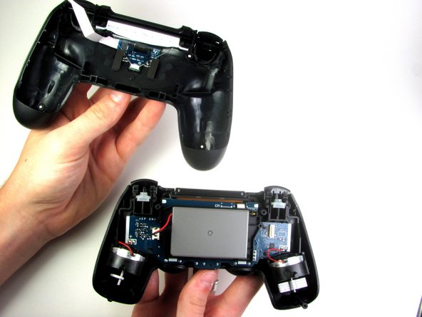
After the two halves are separated, place the top of the controller off to the side.
-
-
-
Using the blunt forceps, remove the battery plug by gently rocking the forceps side-by-side to loosen the plug.
-
After removal of the plug from the motherboard, the battery can be lifted off of the controller.
-
Hasty removal of the battery plug could warp the plastic grips of the plug.
-
-
-
Remove the single 6.0 mm Phillips screw found below the battery retainer with the Phillips #00 Screwdriver.
-
Do not forcefully loosen the screw, as it may amount to permanent damage of the threads, making removal impossible.
-
-
-
Gently detach the touchpad ribbon connected to the motherboard using the blunt forceps. The touchpad ribbon is connected to the motherboard by a connector that flips to tighten and loosen. During reassembly, to reattach the ribbon, the plastic tray will need to be gently removed from the motherboard and the flip-lock flipped up.
-
-
-
Carefully dislodge the motherboard assembly from the front cover.
-
Vibration motors are loosely attached to the motherboard assembly. Provide support at the two ends to ease the separation.
-
When removing the motherboard assembly, try not to tilt the front cover upside down as the buttons and their covers may fall out.
-
-
-
Successful disassembly of the controller will result in the following three parts, respectively:
-
Motherboard Assembly
-
Front Cover
-
Rear Cover
-
-
-
Use a "Helping Hands" or similar tool to hold the circuit board steady for the solder work.
-
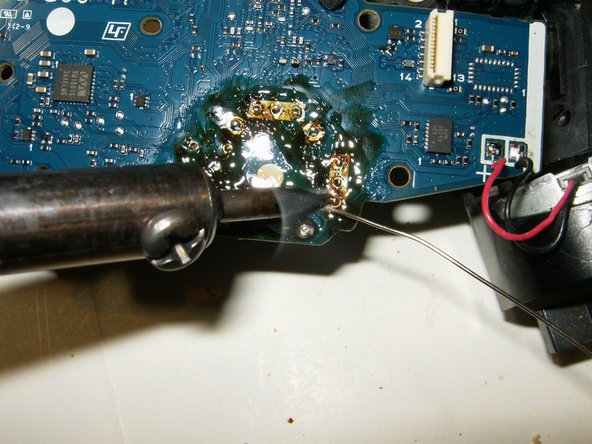
These are the solder connections that will need to be desoldered. Since the board is upside down, left will become right.
-
Use a desoldering wick and flux to melt and remove the solder
-
-
-
Once all the contacts are desoldered, the old joystick can be removed. This may take a bit of practice since all the solder will have to be removed. It does help to pull a bit on the joystick while melting the solder and using the wick.
-
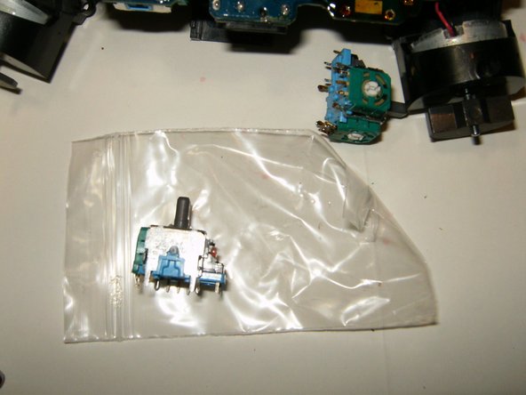
Ensure that the contacts of the replacement joystick are identical to the original.
-
Check that all the holes are cleared of old solder. Hypodermic needles as well as very small drill bits can be used to clear the holes. The molten looking substance on the circuit board is the flux used for the desoldering.
-
-
-
Insert the new joystick into the circuit board. Make sure it is properly seated and that all the contacts line up with the holes in the circuit board.
-
Solder all the contacts to the board.
-
Here is the board after the repair. All that is left is to clean off the old flux with some isopropyl alcohol.
-


Conclusion
To reassemble your device, follow these instructions in reverse order.
Embed this guide
Choose a size and copy the code below to embed this guide as a small widget on your site / forum.
Preview
How To Fix A Broken Analog Stick
Source: https://www.ifixit.com/Guide/DualShock+4+Left+Analog+Stick+Replacement/27764
Posted by: chavarriacrove1962.blogspot.com
0 Response to "How To Fix A Broken Analog Stick"
Post a Comment